
Pulse width modulation (PWM) is a widely-used concept in physics, electronics and telecommunications. It is defined as a form of signal modulation to derive analog waveforms from digital inputs.
In Arduino applications, PWM is useful in varying the intensity of a signal such as the brightness of an LED diode, the ping time of sensors or the power delivery of servomotors.
Why Is PWM Necessary in Arduino?
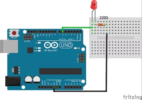
A major reason why PWM techniques are needed in Arduino projects is because it helps generate continuous waveforms. Consider an LED example: any digital signal rests on two values: either it’s ON or OFF, which can be adjusted using Arduino digital pins 5V and 0 respectively, as shown below.
However, there are many applications where you’d be interested in a bit more than the device turning itself off or on. You need a continuous analog waveform to control the brightness or dimness of an LED in smart bulbs.

For example, Philip Hue bulbs have a relevant PWM feature adopted as an Alexa skill: “Alexa, brighten Kitchen to 60%,” a command that can control the brightness of your room.
How to Use PWM in Arduino Projects
The Arduino IDE has several built-in examples to use PWM for various results. To explore the PWM commands in Arduino projects, you can easily install the IDE for Windows 10, Linux or Mac.
You will additionally need to connect an Arduino Uno or Mega board with an LED and manipulate it to an analog function. The components needed include:
- 10 kOhm potentiometer and resistors
- Breadboard and jumper wires
- Arduino IDE
The Arduino Project Hub has a tutorial example where the final circuit is shown, but this is just an unrelated example. Your actual circuit will follow the code and instructions provided in Arduino IDE.
Working Code
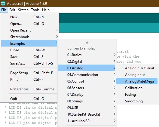
Open Arduino IDE and go to “File -> Examples -> Analog -> AnalogWriteMega.” This sketch fades LEDs up and down one at a time on digital pins 2 through 13. This code is for Arduino Mega board only.
Go through a previous Arduino cheat sheet article to understand the meaning of basic commands including const(), setup(), loop() and delay().
Additionally, there is a for command that sets pins 2 all the way through to 13 as lowest to highest. This means there are 12 possible readings of the LED.
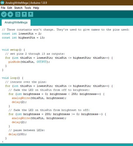
Next, a commmand called analogWrite() is used to control the brightness of the LED from the lowest values at digital pin 2 which is 0, to the highest value for digital pin 13, which is 255. A delay of 100 milli-seconds is introduced to document the transition of LEDs changing their analog status.
Let us take one more example of an LED fading based on analog output. For this, go to “File -> Examples -> Analog” and “Fading.” This can be used with the Arduino Uno board. The LED is attached from digital pin 9 to ground.
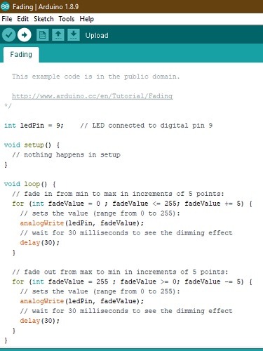
In this example, an analogWrite command was used to modify the fade values in intervals of five from 0 to 255. The dimming is visible at a delay of 30 milli-seconds each for a gradual fading effect.
Conclusion
Pulse width modulations (PWM) are a necessary method in ensuring variability and step advances in your Arduino projects.
Have you used PWM in your own IoT projects? Did you encounter any PWM-like examples in Alexa skills similar to Philip Hue bulbs? Please let us know in the comments.
Get the best of IoT Tech Trends delivered right to your inbox!


