
The tutorial for the project is based on wastage of water due to overflow and wastage of electricity. This happens because of the dry running of the pump in overhead water storage tanks. Hence, we would use Arduino Uno to resolve this problem by building a water tank monitoring system. Let’s understand the significance of this project before building it.
Most of the people in residential areas face the problem of running out of water. Additionally, the overflow of water in tanks is because of an excess supply of water. It becomes difficult for users to judge the level of water in water tanks. When the pump is on, users may not realize the level of water, which may result in an overflow.
A tank monitoring system can sort out the issues associated with a water tank. Thus, it is also possible to check the level of the water using a sensor so that whenever the water goes low, the pump turns on automatically. Also, to avoid the overflow of water, it detects when the water level goes above the set limit, which turns off the pump automatically.
Components for Water Tank Monitoring System
The following components are required to perform the application:
- Arduino Uno R3 board
- Ultrasonic sensor
- Relay board
- 16×2 LCD display with I2C interface
- Buzzer
- 240 V AC submersible pump
- Connecting wires
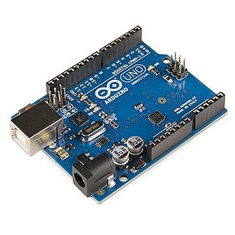
The Arduino Uno R3 board comes with sets of digital and analog input/output (I/O) pins. These feature PWM, RXT, TXD, GPIO, and I2C pin activities. There are a total of 14 digital pins and 6 analog pins on the Arduino Uno R3 board.
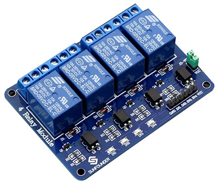
Relays are used to control power appliances like lights, fans, etc. directly from microcontrollers or low voltage circuits. Here we used a four-channel relay board that operates on 5V to control a 240V pump. The relay can handle a maximum of 10A/250V AC or 10A/30V DC. The relay board has three high-power connections: Common (COM), Normally Open (NO), and Normally Closed (NC) with 5V VCC, GND, and control pins.
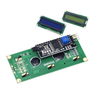
A 16×2 LCD is a very basic module for various devices and display applications. These modules are better than seven-segment and other multi-segment LEDs because they are economical and easy to program for characters and graphics. A 16×2 LCD means it can display 16 characters per line, and two such lines are giving us a considerate space to display our data.
Project Description
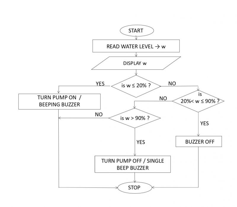
The water level in the tank is continuously monitored by the ultrasonic sensor mounted on top. As the water level in the tank drops below 20 percent, the pump is turned on using the relay mechanism and is kept on until the tank is full. The pump is then turned off and the loop iterated again.
This tutorial focuses on implementing an Arduino-based system to monitor the water level in a tank using an ultrasonic sensor, which also controls a relay-connected pump based on the input from the sensor.
After gathering the required components, it’s time to implement a circuit following the circuit diagram.
Two water levels are set based on the total tank height. The lower level is at 20 percent of the total height, and the upper level is set at 90 percent of the total tank height.
The ultrasonic sensor is mounted on the top of the tank. When the tank is 20 percent full, the distance between the U.S. and the water surface will be:
h20%= Total height – height of 20% filled water
Similarly, when the tank is 90 percent full, the distance between the U.S. and the water surface will be:
h90%= Total height – height of 90% filled water
When the distance of the water surface from the ultrasonic sensor is greater than h20%, the pump is on. The pump is kept on until the set upper water level is achieved, then it automatically turns off. This happens when the distance of the water surface from the ultrasonic sensor is less than h90%.

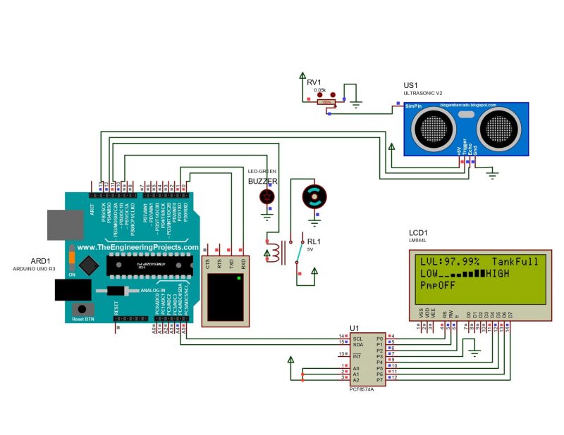
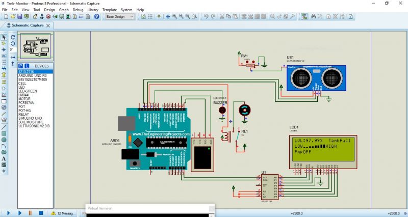
Connecting the Components
Connect a buzzer to pin 10 of the Arduino board and ground its other terminal. The ultrasonic sensor’s Echo and Trigger pins are connected to pins 12 and 13 of the Arduino board respectively.
Now, connect pin 11 of the Arduino to the input pin of the relay board. Connect the pump to the AC circuit of the relay board. Tip: treat the relay board as a switch and complete the AC circuit.
The LCD module, equipped with an I2C interface can be connected by using only two analog pins, which in this case are connected to the A4 and A5 pins of the Arduino board. Now, provide the +Vcc and GND connections to the ultrasonic sensor, relay board, and LCD module using +5V and GND from Arduino.
Arduino IDE Setup
Install the Arduino integrated development environment (IDE) software on your PC, then connect the Arduino board to the PC using the USB cable. Set the board as “Arduino UNO” and port to whichever board is connected in the “Tools” menu of the IDE. You can find the port number by going to the “Device Manager” window on your Windows PC.
Code for Water Tank Monitoring System
Now, create a new sketch and write the following code. You can try to write your own code while keeping in mind which task the microcontroller should do based on a particular input.
#include <Wire.h>
#include <LiquidCrystal_I2C.h>
#define trigger 13
#define echo 12
#define motor 11
#define buzzer 10

LiquidCrystal_I2C lcd(0x3F,20,4);
float time=0,distance=0,percentage;
int temp=0,HT=110; //tank ht

//Bar Graph
byte Level0[8] = {
0b00000,
0b00000,
0b00000,
0b00000,
0b00000,
0b00000,
0b11111,
0b11111
};

byte Level1[8] = {
0b00000,
0b00000,
0b00000,
0b00000,
0b11111,
0b11111,
0b11111,
0b11111
};

byte Level2[8] = {
0b00000,
0b00000,
0b11111,
0b11111,
0b11111,
0b11111,
0b11111,
0b11111
};

byte Level3[8] = {
0b11111,
0b11111,
0b11111,
0b11111,
0b11111,
0b11111,
0b11111,
0b11111
};

byte NoLevel[8] = {
0b00000,
0b00000,
0b00000,
0b00000,
0b00000,
0b00000,
0b00000,
0b00000,
};

void setup()
{
Serial.begin (9600);
lcd.init();
lcd.backlight();
pinMode(trigger,OUTPUT);
pinMode(echo,INPUT);
pinMode(motor, OUTPUT);
pinMode(buzzer, OUTPUT);
digitalWrite(motor, HIGH);
lcd.print(" Tank Monitor ");
lcd.setCursor(0,1);
lcd.print(" System ");
digitalWrite(buzzer, HIGH);
delay(400); //2000
digitalWrite(buzzer, LOW);
lcd.createChar(0, Level0);
lcd.createChar(1, Level1);
lcd.createChar(2, Level2);
lcd.createChar(3, Level3);
lcd.createChar(4, NoLevel);
lcd.clear();
}

void loop()
{
digitalWrite(trigger,LOW);
delayMicroseconds(2);
digitalWrite(trigger,HIGH);
delayMicroseconds(10);
digitalWrite(trigger,LOW);
delayMicroseconds(2);
time=pulseIn(echo,HIGH);
distance=time<em>340/20000; percentage=100</em>(1-(distance/HT));
lcd.setCursor(0,0);
lcd.print("LVL:");
lcd.print((percentage));
lcd.print("% ");
if(percentage>90.0 && temp==0)
{
digitalWrite(motor, HIGH);
digitalWrite(buzzer, HIGH);
lcd.setCursor(12,0);
lcd.print("TankFull");
lcd.setCursor(0,2);
lcd.print("PmpOFF");
if(percentage>75 && percentage<=100)
HundredPercentage();
digitalWrite(buzzer, LOW);
temp=1;
}

else if(percentage>90.0 && temp==1)
{
digitalWrite(motor, HIGH);
lcd.setCursor(12,0);
lcd.print("TankFull");
lcd.setCursor(0,2);
lcd.print("PmpOFF");
if(percentage>75 && percentage<=100)
HundredPercentage();
}

else if(percentage<20.0)
{
digitalWrite(motor, LOW);
lcd.setCursor(0,1);
lcd.print(" ");
lcd.setCursor(0,1);
lcd.print("LOW LVL");
lcd.setCursor(0,2);
lcd.print("PmpON");
digitalWrite(buzzer, HIGH);
delay(100);
digitalWrite(buzzer, LOW);
temp=0;
}

else if(percentage>20 && percentage<=25)
TwentyFivePercentage();

else if(percentage>25 && percentage<=50)
FiftyPercentage();

else if(percentage>50 && percentage<=75)
SeventyFivePercentage();

else if(percentage>75 && percentage<=100)
HundredPercentage();

if(digitalRead(motor)==HIGH)
{
lcd.setCursor(0,2);
lcd.print("PmpOFF");
}

if(digitalRead(motor)==LOW)
{
lcd.setCursor(0,2);
lcd.print("PmpON");
}

lcd.setCursor(4,0);
lcd.print(" ");
lcd.setCursor(3,2);
lcd.print(" ");
lcd.setCursor(13,2);
lcd.print(" ");
lcd.setCursor(0,3);
lcd.print(" ");
}

void ZeroPercentage()
{ lcd.setCursor(0, 1);
lcd.print("LOW");
lcd.setCursor(3, 1);
lcd.print(" ");
lcd.setCursor(3, 1);
lcd.write(byte(4));
lcd.setCursor(4, 1);
lcd.write(byte(4));
lcd.setCursor(5, 1);
lcd.write(byte(4));
lcd.setCursor(6, 1);
lcd.write(byte(4));
lcd.setCursor(7, 1);
lcd.write(byte(4));
lcd.setCursor(8, 1);
lcd.write(byte(4));
lcd.setCursor(9, 1);
lcd.write(byte(4));
lcd.setCursor(10, 1);
lcd.write(byte(4));
lcd.setCursor(11, 1);
lcd.print("HIGH");
}

void TwentyFivePercentage()
{ lcd.setCursor(0, 1);
lcd.print("LOW");
lcd.setCursor(3, 1);
lcd.print(" ");
lcd.setCursor(3, 1);
lcd.write(byte(0));
lcd.setCursor(4, 1);
lcd.write(byte(0));
lcd.setCursor(5, 1);
lcd.write(byte(4));
lcd.setCursor(6, 1);
lcd.write(byte(4));
lcd.setCursor(7, 1);
lcd.write(byte(4));
lcd.setCursor(8, 1);
lcd.write(byte(4));
lcd.setCursor(9, 1);
lcd.write(byte(4));
lcd.setCursor(10, 1);
lcd.write(byte(4));
lcd.setCursor(11, 1);
lcd.print("HIGH");
}

void FiftyPercentage()
{ lcd.setCursor(0, 1);
lcd.print("LOW");
lcd.setCursor(3, 1);
lcd.print(" ");
lcd.setCursor(3, 1);
lcd.write(byte(0));
lcd.setCursor(4, 1);
lcd.write(byte(0));
lcd.setCursor(5, 1);
lcd.write(byte(1));
lcd.setCursor(6, 1);
lcd.write(byte(1));
lcd.setCursor(7, 1);
lcd.write(byte(4));
lcd.setCursor(8, 1);
lcd.write(byte(4));
lcd.setCursor(9, 1);
lcd.write(byte(4));
lcd.setCursor(10, 1);
lcd.write(byte(4));
lcd.setCursor(11, 1);
lcd.print("HIGH");
}

void SeventyFivePercentage()
{ lcd.setCursor(0, 1);
lcd.print("LOW");
lcd.setCursor(3, 1);
lcd.print(" ");
lcd.setCursor(3, 1);
lcd.write(byte(0));
lcd.setCursor(4, 1);
lcd.write(byte(0));
lcd.setCursor(5, 1);
lcd.write(byte(1));
lcd.setCursor(6, 1);
lcd.write(byte(1));
lcd.setCursor(7, 1);
lcd.write(byte(2));
lcd.setCursor(8, 1);
lcd.write(byte(2));
lcd.setCursor(9, 1);
lcd.write(byte(4));
lcd.setCursor(10, 1);
lcd.write(byte(4));
lcd.setCursor(11, 1);
lcd.print("HIGH");
}

void HundredPercentage()
{ lcd.setCursor(0, 1);
lcd.print("LOW");
lcd.setCursor(3, 1);
lcd.print(" ");
lcd.setCursor(3, 1);
lcd.write(byte(0));
lcd.setCursor(4, 1);
lcd.write(byte(0));
lcd.setCursor(5, 1);
lcd.write(byte(1));
lcd.setCursor(6, 1);
lcd.write(byte(1));
lcd.setCursor(7, 1);
lcd.write(byte(2));
lcd.setCursor(8, 1);
lcd.write(byte(2));
lcd.setCursor(9, 1);
lcd.write(byte(3));
lcd.setCursor(10, 1);
lcd.write(byte(3));
lcd.setCursor(11, 1);
lcd.print("HIGH");
}
Verify and Upload
Now you need to verify the code by pressing the verify button on the Arduino IDE toolbar. Wait for the code to verify. Once verified, you can see a “Done compiling” message on the screen.
If no errors were found, upload the code using the upload button beside the verify button. Wait for the code to get uploaded for the circuit to start working. You will also see a “Done uploading” message on the screen.
Code Explanation for Water Tank Monitoring System Using Arduino Uno
Firstly, all the required libraries are imported by the header files. The variables and pins are declared in the next step. The display characters for the bar graph are also defined here.
Void Setup
The void setup function runs once, initializing all the required pins on the Arduino board.
LCD module’s backlight is initialized here. LCD prints “Tank Monitor System” with a buzzer beep.
Void Loop
The void loop function runs the code repeatedly. First, the ultrasonic sensor sends an ultrasonic wave, which is reflected back from the water surface. The Arduino board calculates the time interval between sending and receiving the wave and converts it into the distance which is then stored in the distance variable.
Now, based on the distance value, the percentage of water level in the tank is calculated and also displayed on the LCD module. The if and else condition statement after that is executed for different cases of water levels, and accordingly, a signal is sent to the relay board for turning the pump on or off.
Conclusion
Making an IoT-based tank monitor system gives real-time information about the current water level in the tank and also automates the process of filling the water tank, thus saving electricity and water. An Arduino UNO board is the brain of the system, which takes input from the ultrasonic sensor, processes it and displays it on an LCD module, and also controls the pump via a relay board accordingly.
Get the best of IoT Tech Trends delivered right to your inbox!


