
Whether it’s for a micromouse robot or a tiny IoT electric fan, knowing how to make things run using DC motors with the Raspberry Pi can unlock a broad range of creative DIY projects to keep you busy. For this guide, we are using an L298N motor controller in Raspberry Pi to send electricity to a pair of DC motors and make them spin!
Why the L298N Motor Controller Module?
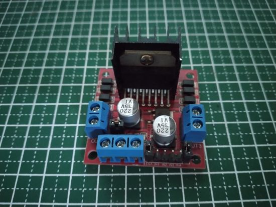
The L298N motor controller module is a board that helps microcontrollers and microprocessors like the Raspberry Pi power DC motors that require more than the 3.3V or 5V they can supply.
It uses the L298N integrated circuit, powers all the logic and energy management needed to run motors, and isolates the Raspberry Pi from the higher voltage being run to the DC motors.
The L298N module is a staple motor controller in beginners’ DIY robotics kits because of its ease of use. It has header pins where you can insert jumper wires, connecting it to the Raspberry Pi without a hitch. You can also speed up or slow down the motors by applying pulse width modulation (PWM) signals to its “enable” pins.
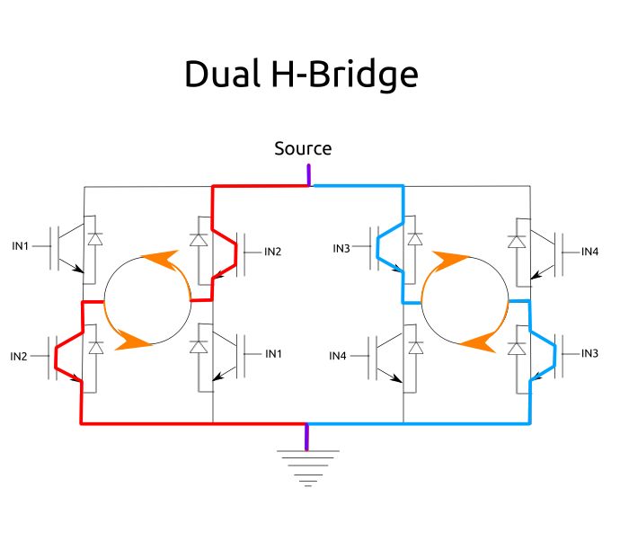
On the circuitry side, the L298N is a form of a dual H-bridge circuit. It is actually a pair of H-bridge circuits, which is made out of a motor with four electronic switches. This allows you to set the direction of the current without having to physically rewire the motor. Reversing the current on one H-bridge also reverses the direction of the motor’s spin. The L298N has two of these, letting you control a pair of motors independently.
With that in mind, it’s time to get your hands working on some motors.
Related: you may also interested in using a servo motor with the Raspberry Pi.
What You’ll Need
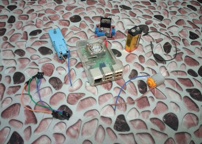
- DC motor x2 – either brushed or brushless should be fine; you can use motors with or without a gearbox. Look for DC motors with a 35V max rating.
- L298N motor controller module
- DC power supply source – either a 9V battery and connector or a variable Power Supply Unit (PSU) if available.
- Female-to-female jumper wires x6
- Male-to-female jumper wire x1
- Raspberry Pi board – any make or model should work, except for the Pico.
Optional supplies:
- Soldering iron – to add wires on your motors if they aren’t pre-soldered with wires.
- Wire strippers
- Wire cutter
- PVC copper wires – 12AWG, preferably stranded, to be soldered to the DC motors.
How to Use a DC Motor and L298N Motor Controller Module With Your Raspberry Pi
1. Making the Code
- Import the necessary modules.
import RPi.GPIO as GPIO
from time import sleep
- Define the pins. The left motor will be controlled by pins 7, 11, and 13, while the right motor will be controlled by pins 8, 10, and 12.
leftForward = 7
leftBackward = 11
leftEnable = 13

rightForward = 8
rightBackward = 10
rightEnable = 12
- Build the board-related settings.
GPIO.setwarnings(False)
GPIO.setmode(GPIO.BOARD)
- It’s time to set the pin designations. Because the L298N DC controller module only requires input from the Raspberry Pi, designate the Raspberry Pi’s pins as output pins.
GPIO.setup(leftForward, GPIO.OUT)
GPIO.setup(leftBackward, GPIO.OUT)
GPIO.setup(leftEnable, GPIO.OUT)
GPIO.setup(rightForward, GPIO.OUT)
GPIO.setup(rightBackward, GPIO.OUT)
GPIO.setup(rightEnable, GPIO.OUT)
- Set the left and right enable pins to PWM so that it’s possible to set the speed of the motors by controlling the voltage output of each pin. We talked about how PWM works in a previous article about controlling servos.
leftEnPWM = GPIO.PWM(leftEnable, 100)
leftEnPWM.start(50)
GPIO.output(leftEnable, GPIO.HIGH)

rightEnPWM = GPIO.PWM(rightEnable, 100)
rightEnPWM.start(50)
GPIO.output(rightEnable, GPIO.HIGH)
- Make a while loop.
while True:
        GPIO.output(leftForward, GPIO.HIGH)
        GPIO.output(rightForward, GPIO.HIGH)
        sleep(1)
        leftEnPWM.ChangeDutyCycle(100)
        rightEnPWM.ChangeDutyCycle(100)
        sleep(1)
        leftEnPWM.ChangeDutyCycle(50)
        rightEnPWM.ChangeDutyCycle(50)
        sleep(1)
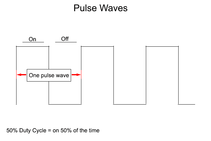
Within the while loop, start by turning on the leftForward and rightForward pins for one second. To control the speed, change the duty cycle of the enable pins. First set them to 100% duty cycle for one second, then set them to 50% for another. At 100% duty cycle, the motors will run at max speed, while at 50%, they will run at half speed.
- Stop the motors by turning off the leftForward and rightForward pins. Here, we’re stopping them for one second.
        GPIO.output(leftForward, GPIO.LOW)
        GPIO.output(rightForward, GPIO.LOW)
        sleep(1)
- Repeat that same process but by run the motors backward instead.
        GPIO.output(leftBackward, GPIO.HIGH)
        GPIO.output(rightBackward, GPIO.HIGH)
        sleep(1)
        leftEnPWM.ChangeDutyCycle(100)
        rightEnPWM.ChangeDutyCycle(100)
        sleep(1)
        leftEnPWM.ChangeDutyCycle(50)
        rightEnPWM.ChangeDutyCycle(50)
        sleep(1)
        GPIO.output(leftBackward, GPIO.LOW)
        GPIO.output(rightBackward, GPIO.LOW)
        sleep(1)
Here’s the full version of the code:
import RPi.GPIO as GPIO
from time import sleep

leftForward = 7
leftBackward = 11
leftEnable = 13

rightForward = 8
rightBackward = 10
rightEnable = 12

GPIO.setwarnings(False)
GPIO.setmode(GPIO.BOARD)

GPIO.setup(leftForward, GPIO.OUT)
GPIO.setup(leftBackward, GPIO.OUT)
GPIO.setup(leftEnable, GPIO.OUT)
GPIO.setup(rightForward, GPIO.OUT)
GPIO.setup(rightBackward, GPIO.OUT)
GPIO.setup(rightEnable, GPIO.OUT)

leftEnPWM = GPIO.PWM(leftEnable, 100)
leftEnPWM.start(50)
GPIO.output(leftEnable, GPIO.HIGH)

rightEnPWM = GPIO.PWM(rightEnable, 100)
rightEnPWM.start(50)
GPIO.output(rightEnable, GPIO.HIGH)

while True:
        GPIO.output(leftForward, GPIO.HIGH)
        GPIO.output(rightForward, GPIO.HIGH)
        sleep(1)
        leftEnPWM.ChangeDutyCycle(100)
        rightEnPWM.ChangeDutyCycle(100)
        sleep(1)
        leftEnPWM.ChangeDutyCycle(50)
        rightEnPWM.ChangeDutyCycle(50)
        sleep(1)
        GPIO.output(leftForward, GPIO.LOW)
        GPIO.output(rightForward, GPIO.LOW)
        sleep(1)

        GPIO.output(leftBackward, GPIO.HIGH)
        GPIO.output(rightBackward, GPIO.HIGH)
        sleep(1)
        leftEnPWM.ChangeDutyCycle(100)
        rightEnPWM.ChangeDutyCycle(100)
        sleep(1)
        leftEnPWM.ChangeDutyCycle(50)
        rightEnPWM.ChangeDutyCycle(50)
        sleep(1)
        GPIO.output(leftBackward, GPIO.LOW)
        GPIO.output(rightBackward, GPIO.LOW)
        sleep(1)
Save this as “rpi-dcmotor.py” or any other filename, as long as it ends with the “.py” file extension. Shut down your Raspberry Pi after this.
2. Building the Circuit
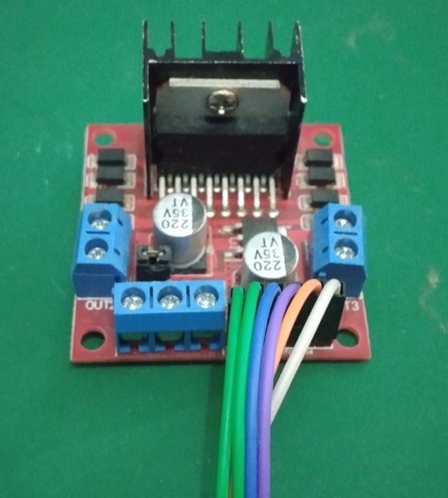
- Moving on to the L298N motor controller module, if you look at the header pins, you should see jumper headers connecting the ENA and ENB pins to each 5V pin. Remove these jumper headers from the board.
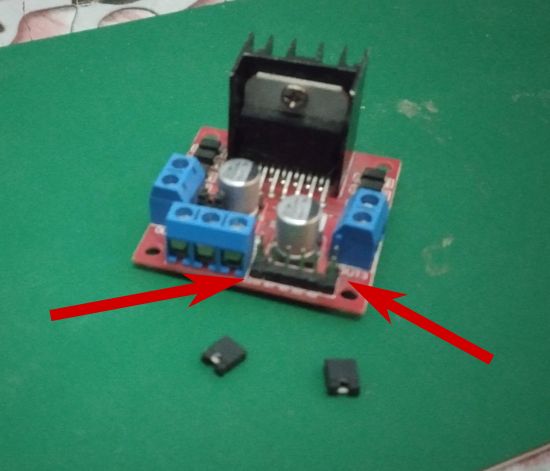
Note: These jumper pins automatically connect the EN pins to 5V, “enabling” you to control the circuit through the IN pins. While you’re still supposed to pass electricity through this pin, the 5V may cause some problems for the Raspberry Pi, which is meant to use 3.3V instead of 5V. Plus, connecting these pins to the Raspberry Pi lets you control the motors’ speeds later on.
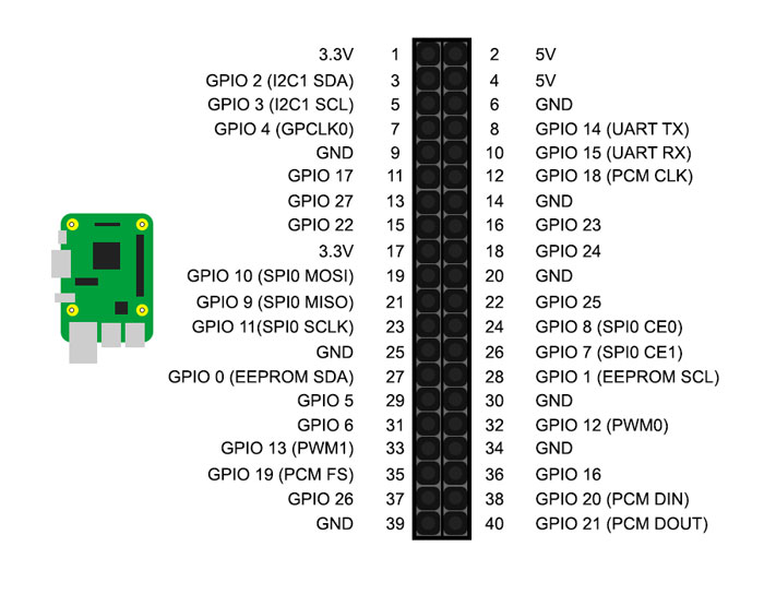
- Use female-to-female jumper wires to connect the header pins to the Raspberry Pi. For this guide, you’ll have to connect them to these Raspberry Pi pins:
- IN1 = pin 7
- IN2 = pin 11
- ENA = pin 13
- IN3 = pin 8
- IN4 = pin 10
- ENB = pin 12
Tip: To find out which pin number is which on the Raspberry Pi, hold it so that the GPIO pins sit to the right. Those are the tiny metal bits standing on a black tray. Then, if you look at the top left pin from that tray, that’s pin 1. To its right is pin 2. Below pin 1 is pin 3, and so on.
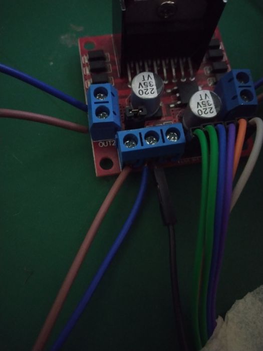
- Connect a jumper wire to the L298N’s GND screw terminal. On the Raspberry Pi, connect the other side of this jumper wire to pin 9.
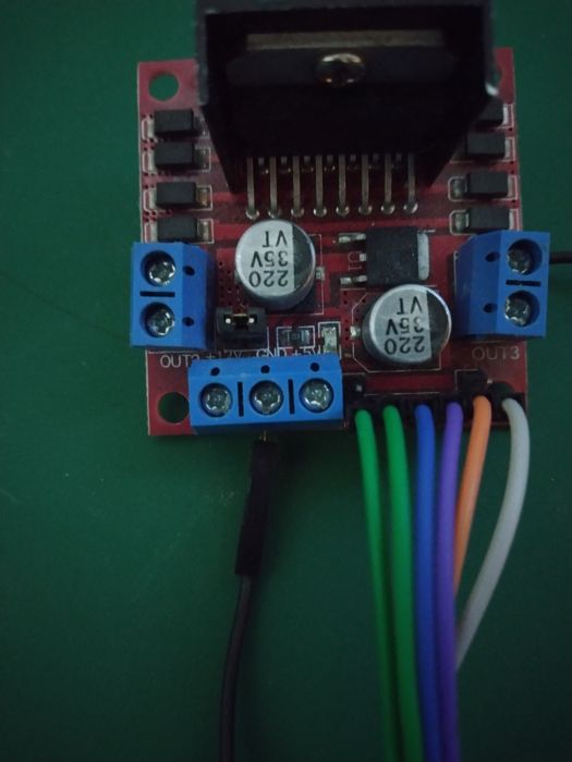
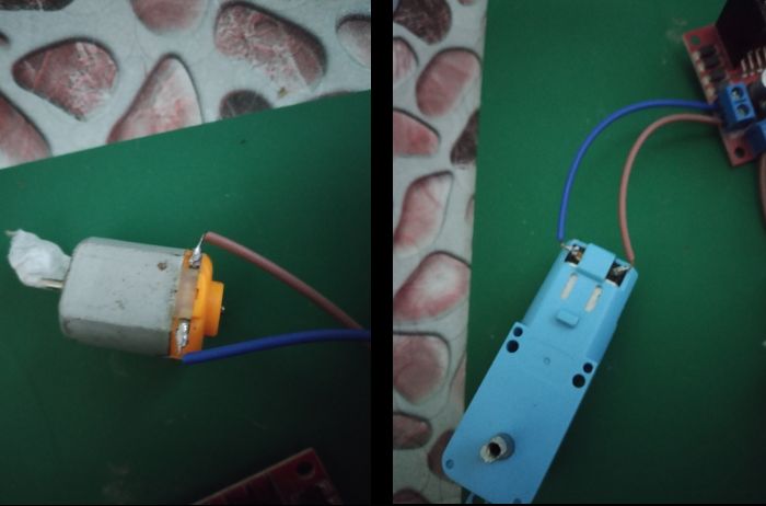
- For the motors, you can insert them in any direction you want. Just make sure that motor 1 is connected to OUT1 and OUT2, and motor 2 to OUT3 and OUT4.
Note: most DC motors usually don’t have soldered wires. You can solder them on your own. Any gauge can work, but stranded copper wires work best.
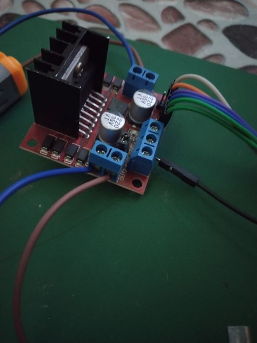
- For the power supply, first make sure that it’s turned off or disconnected. Point the positive part to the “+12V” side and the negative part to GND, along with the GND jumper wire to the Raspberry Pi.
3. Making It Work
You can start the code by running the script on the terminal. But before that, you have to add power to the L298N module.
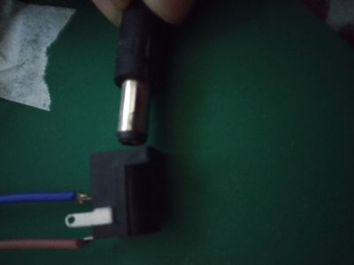
The L298N DC motor controller module can take any DC power source as long as it does not exceed 45V. Availability-wise, it would be easier to use a 9V battery with a DC barrel jack connected to the module’s power terminals.
You also don’t have to worry about the 9V battery ruining your Raspberry Pi. The L298N module uses a special chip called a MOSFET that works like a low-power relay, becoming an electric switch that keeps your pins somewhat isolated from the power supply.
Putting Everything Together
How does emitting electricity from one pin makes a DC motor spin? Let’s delve a little deeper into how we’re making the motors spin.
Controlling Motor Spin
The L298N motor controller module uses multiple electric switches to control the spin of a motor. You can think of these switches as something like a wall switch, except they don’t use fingers to work – they use the 3.3V from the Raspberry Pi.
And this is where the GPIO.output(<insert-pin-here>, GPIO.HIGH) comes into play. Setting that pin to GPIO.HIGH makes the said pin emit 3.3V. This activates the switch, which allows electricity to enter the motor. The flow of electricity then makes the motor spin. Turning these pins to GPIO.LOW turns the switch off, cutting power to the motor.
We can make the motor spin backward by reversing the flow of electricity through the motor. This is why we have two separate pins controlling one motor’s spin: the backward pin and the forward pin. These control the electric switches on either side of the motor’s power supply, sending electricity forward or backward.
Setting Motor Speed
There is also the case with speed. Compared to the forward and backward pins, the enable pins control how much electricity passes through the motor at any given point of time.
By increasing the voltage on the enable pins, their switches sort of open “wider” and allow more electricity to pass through the motors. Adding more electricity through the motors makes them spin faster. Reducing it makes them slower.
On the Raspberry Pi, we use PWM, or Pulse With Modulation, to control the voltage output of a pin. Increasing the duty cycle brings the voltage close to 3.3V at max, and decreasing it brings it closer to 0V.
In fact, you can somehow “turn off” the motors by bringing their enable pins to 0V. Think of this as something similar to a car: the enable pins bring the gas that powers the motors, while the forward and backward pins shift the gears that make them run straight on or back in reverse.
Tips: other than DC motors, you can also use a Piezo speaker with the Raspberry Pi to play sound.
Frequently Asked Questions
What is the difference between a brushed and brushless DC motor?
These two differ based on where their electromagnet coils are. Brushed DC motors have their coils in the middle, turning between a circle of permanent magnets. Brushless DC motors have their coils on the opposite side – their electromagnetic coils around permanent magnets.
Which is better: brushed motors or brushless motors?
Brushed motors are cheap and have good performance at low speeds. However, they tend to heat up faster than brushless motors and are less energy-efficient. On the other hand, brushless motors can reach faster rotation speeds compared to brushed motors, overheat less, and use less electricity to spin faster.
If you are using motors inside gearboxes for Raspberry Pi robot wheels, brushed motors should be better. But if you are using non-geared motors, like in a tiny electric fan, then brushless motors should be better.
What is the maximum current output of the L298N motor driver module?
While this can depend on the manufacturer, you can expect a peak current of 2A per motor on the L298N motor driver module.
Photos and diagrams by Terenz Jomar Dela Cruz.
Get the best of IoT Tech Trends delivered right to your inbox!


