
DC motors are great, but it’s hard to make them control robotic hands and fingers. You just can’t get the angle right. But with servo motors, you can always be sure that they’ll stop at the right angle all the time.
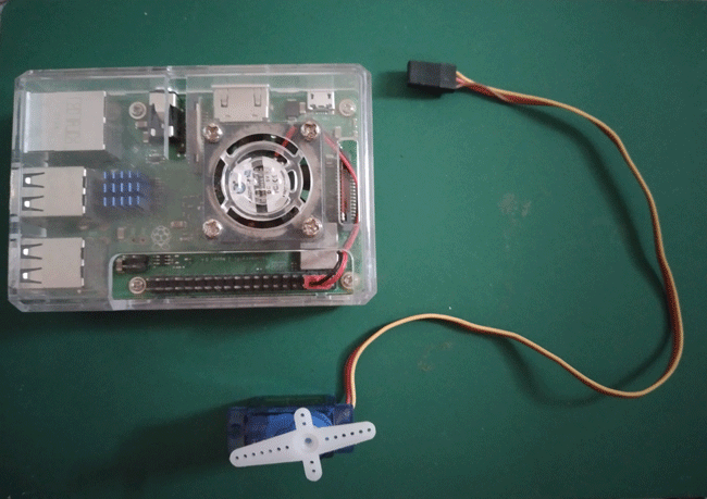
So pick up your jumper wires, and we’ll spin a servo motor with the Raspberry Pi and make it stop at any angle!
What Is a Servo Motor?
A servo motor is a DC motor that lets you control its angle. You can set it to turn 90 degrees, stop, then go back 90 degrees. They’re useful when you need precision on an automatically-moving part.
Inside a servo motor are three parts: DC motor, potentiometer, and a circuit that controls the motor.
The potentiometers in servo motors are resistors, just like the resistors you use when lighting up LEDs. The exception is that they can change resistance values when you turn them.
In servo motors, the potentiometer is geared to the DC motor so that it will turn when the DC motor spins. This lets you know the motor shaft’s angle. The controller circuit tells it to stop when it reaches a certain angle.
With that in mind, using servo motors with the Raspberry Pi means you’re telling the controller circuit to spin the DC motor until it reaches a certain angle.
What Is Pulse Width Modulation?
Pulse Width Modulation (PWM) is the heart of this whole servo-moving thing. It’s a method of controlling the timing between pulse waves in a PWM signal.
As a more layman-friendly explanation, imagine the Raspberry Pi emitting 3.3V from pin 7. On an oscillator making a graph of voltage over time, that would make a plot on the 3.3V side, which becomes a long line as time passes by. When it suddenly drops to 0V, the oscillator makes a vertical line to the 0V side, then makes a horizontal line from there over time.
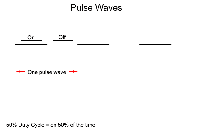
That is called a pulse wave. PWM is when you control either the distance between two pulse waves (length of 0s) or the length of the pulse itself (length of 1s). This is also known as a duty cycle and is what you change while using the ChangeDutyCycle() function.
PWM control is an important function in many microcontrollers, not just the Raspberry Pi. It lets you control and output so much other stuff, all the while just using a tiny bit of electricity to work.
Things You Need to Spin a Servo Motor
- Servo motor
- 3 Jumper wires
- Raspberry Pi (any model except the Pico)
Steps to Using a Servo Motor
- With your favorite code editor, paste the following code:
import RPi.GPIO as GPIO
from time import sleep

servoPin = 7
GPIO.setwarnings(False)
GPIO.setmode(GPIO.BOARD)
GPIO.setup(servoPin, GPIO.OUT)
pin7 = GPIO.PWM(servoPin, 50)
pin7.start(0)

def angleToDutyConvert(angle):
  dutyCycle = angle / 18 + 2
  GPIO.output(servoPin, GPIO.HIGH)
  pin7.ChangeDutyCycle(dutyCycle)
  sleep(0.15)
  GPIO.output(servoPin, GPIO.LOW)
  sleep(0.15)

def sweep(degrees):
  for pos in range(0, degrees, +5):
    print(pos)
    angleToDutyConvert(pos)
  for pos in range(degrees, 0, -5):
    print(pos)
    angleToDutyConvert(pos)

while True:
  sweep(45)
  sweep(90)
- Save as “rpi-servo.py” or any filename of your choice, as long as it ends with the “.py” file extension. Shut down your Raspberry Pi afterward.
- It’s time to build the circuit! Servos come with three wires that are usually stuck together as a single, flat cable.
Servo wires can come in different colors, depending on the manufacturer. Wire them to the Raspberry Pi like as follows:
- White, red, black: white = pin 7, red = 5V, black = GND
- Yellow, red, brown: yellow = pin 7, red = 5V, black = GND
- Blue, red, black: blue = pin 7, red = 5V, black = GND
The wire you’re connecting to pin 7 is the servo’s “signal” wire. This is connected straight to the controller circuit.
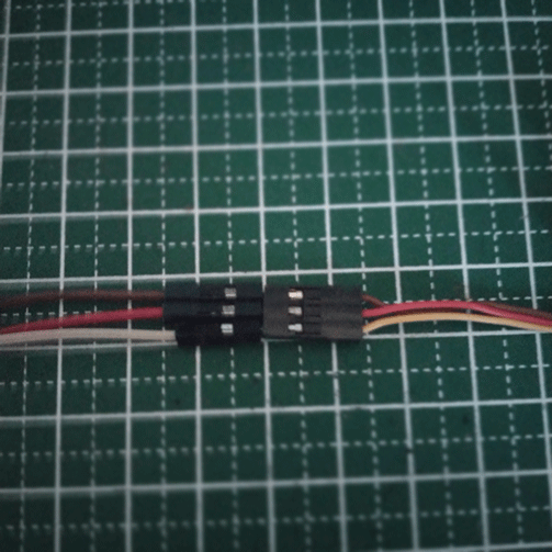
If you don’t have enough male-to-female jumper wires, you can make your own with a male-to-male and a female-to-female jumper wire connected together.

Tip: If you’re having trouble looking for pin 7, hold your Raspberry Pi in a way that the GPIO pins are placed on the right. Starting from the top-left pin, that would be pin 1. To the right of it is pin 2. Below pin 1 is pin 3 and so on.

The pinout is universal across in all 40-pin Raspberry Pi models.
- power up your Raspberry Pi and open the terminal. Use
cdto open the folder where you saved the file. An example iscd MTE/experiments. You can also do this wirelessly via SSH. - It’s time to run the Python script. Enter
python3 rpi-servo.pyand watch your servo move!
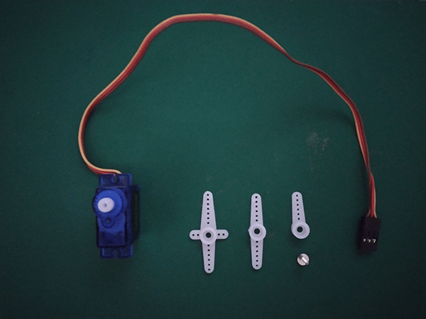
Tip: it’s easier to see the Raspberry Pi move when you place a piece of tape on it, but ideally, you should use the “horn” that comes with the servo straight from the box.
How It Works
As with most of the other instructions we do, we are dividing this code into four parts:
- Import Commands
- Setup Commands
- Function Declarations
- Looped Commands
As always, these are not “standard” divisions. It’s just good practice to divide your code into smaller bits when programming things to make editing and debugging much easier!
Import Commands
The import commands section is where you’re supposed to load your modules. Here, we’re using two modules: RPi.GPIO and time.
import RPi.GPIO as GPIO
from time import sleep
import RPi.GPIO as GPIO imports the RPi.GPIO module and lets you control the black pins (GPIO) where you fit the code wires in. The latter part of this line, as GPIO, declares a new variable named GPIO. Here, GPIO will always mean RPi.GPIO, unless changed in the later part of the code. You can replace GPIO with any other variable name you want!
from time import sleep is another way to import a module, but instead of importing the whole module, you’re only importing part of it. Here, we just took the sleep part of the time module, which lets you use the sleep() function, pausing the code for a given amount of seconds.
Setup Commands
Setup commands let you set up and define things before going to the looped part.
servoPin = 7
GPIO.setwarnings(False)
GPIO.setmode(GPIO.BOARD)
GPIO.setup(servoPin, GPIO.OUT)
pin7 = GPIO.PWM(servoPin, 50)
pin7.start(0)
servoPin = 7 defines the variable servoPin and gives it the value 7. We’re using this to say that the pin for controlling the servo motor will be pin 7.
Why define a pin number? Sometimes, when you change your mind and think, you want to move it to pin 40, for example, then it’s easier to change just one pin number than have to look for the number 7 all over your code.
GPIO.setwarnings(False) stops a warning message you will see when you run a Python script that uses the GPIO pins. It’s set to “True” by default.
GPIO.setmode(GPIO.BOARD) defines which pinout you’re using. There are two types: BOARD and BCM. In BOARD, you’re defining pins based on where they are. Pin 1 is at the top left, pin 2 to its right, and so on.
BCM stands for “Broadcom” and picks pins based on their Broadcom SOC channel. This is a pin-specific number. Unlike BOARD, it’s easier to make mistakes with BCM, as the pin number you’re going to use changes based on which Raspberry Pi model you’re using.
GPIO.setup(servoPin, GPIO.OUT) defines pin 7, that pin we defined earlier as servoPin, and assigns it as an output pin.
pin7 = GPIO.PWM(servoPin, 50) is another variable we’re defining. GPIO.PWM(servoPin, 50) means that you’re making the servoPinoutput pin release a PWM signal. We’ll talk about PWM (Pulse Width Modulation) later. But to sate some curiosity, PWM means you’re turning the pin on and off at regular intervals. The second part, 50, tells the pin to be turned on to 50% of the interval, then turn off.
Lastly, pin7.start(0) makes pin 7 start doing the PWM thing, making it ready to go!
Function Declarations
Programming complex code can be done in two ways: type and retype the same thing over and over and over again or type it once in a variable and reduce ten lines of code into one line. “Function” makes that easier, and no programmer in their right mind would favor the former over a nice function.
def angleToDutyConvert(angle):
  dutyCycle = angle / 18 + 2
  GPIO.output(servoPin, GPIO.HIGH)
  pin7.ChangeDutyCycle(dutyCycle)
  sleep(0.15)
  GPIO.output(servoPin, GPIO.LOW)
  sleep(0.15)

def sweep(degrees):
  for pos in range(0, degrees, +5):
    print(pos)
    angleToDutyConvert(pos)
  for pos in range(degrees, 0, -5):
    print(pos)
    angleToDutyConvert(pos)
The functions in the declarations are just one giant “function in a function.” We are starting at the bottom function, sweep(), first, which uses the other function, angleToDutyConvert(), inside it.
Function #1: sweep(degrees)
def sweep(degrees): defines a function name, sweep, and gives it one parameter: degrees. We want this function to take an angle in degrees and sweep slowly until it reaches that angle. That’s while it prints out the current angle as it moves, so you’ll already know how far it’s gone.
def sweep(degrees):
  for pos in range(0, degrees, +5):
    print(pos)
    angleToDutyConvert(pos)
  for pos in range(degrees, 0, -5):
    print(pos)
    angleToDutyConvert(pos)
Normally, servo motors will move to a target angle as fast as they can. To make a servo motor “sweep” slowly, we’ll have to make it move and stop at a small angle until it reaches the target angle.
To do that, we need a “for” loop. The line for pos in range(0, degrees, +5): is a for loop that saves the current position in degrees to a variable, pos, and loops between the starting part of the range() function, 0, and the max value in degrees while incrementing by 5.
You can visualize it like this: The value for pos starts at 0, then moves by +5. The for loop checks whether it’s still below the max value (the degrees part). If it’s not, then it starts doing what’s inside the loop, then goes back to add +5 to pos. Since it used to be 0, the next value should be 0 + 5 = 5. It checks again and repeats until pos becomes either bigger or at the same level as degrees.
The next part does things in reverse. Starting from the value of degrees, the servo will move by -5 until the value of posgoes down to 0.
You may notice that each for loop has two lines: print(pos) and angleToDutyConvert(pos). The first one, print(pos), prints the value of pos into the console, which makes things easier to see. angleToDutyConvert(pos), on the other hand, is that custom function in our function.
Function #2: angleToDutyConvert(pos)
While this was mentioned earlier, it’s easier to explain after explaining what it’s going to be used in. angleToDutyConvert(angle) is a custom function, like sweep(degrees). So what’s this for?
def angleToDutyConvert(angle):
  dutyCycle = angle / 18 + 2
  GPIO.output(servoPin, GPIO.HIGH)
  pin7.ChangeDutyCycle(dutyCycle)
  sleep(0.15)
  GPIO.output(servoPin, GPIO.LOW)
  sleep(0.15)
Remember that sweep(degrees) takes in a number in degrees. That’s great, but computers (and the servo’s controller circuit) don’t know what a “degree” is, yet they do know duty cycles.
For most servo motors, they figure out the “angle” by listening to duty cycles. To convert a number from degrees to duty cycles, you should divide the angle by 18 and add 2 to the quotient. That’s exactly what the line dutyCycle = angle / 18 + 2 is for.
The next part of the function does most of the legwork. GPIO.output(servoPin, GPIO.HIGH) turns pin 7 on, sending a signal to the servo motor. pin7.ChangeDutyCycle(dutyCycle) changes the duty cycle with the value from converting degrees to duty cycles, then sleep(0.15) pauses the code for 0.15 seconds.
The last two parts, GPIO.output(servoPin, GPIO.LOW) and a second sleep(0.15), temporarily turn pin 7 off. They’re not much of a “vital” code but help with jittering, especially when you want the servo to hold its position.
Looped Commands
It’s time to make things work. Using a while loop, turn the servo motor with the Raspberry Pi for as long as you’d like.
while True:
  sweep(45)
  sweep(90)
while True: is a while loop that never ends. Whatever you place inside it will get repeated forever, as long as you feed it electricity.
But the real MVP here is the sweep() function, which is that function we made earlier. You can add more of these to make the servo motor sweep at different angles. Just remember that whatever number you put between the parentheses, that’s going to be the angle the servo will move in.
Frequently Asked Questions
Why does my Raspberry Pi's red indicator LED die while using a servo motor?
The red indicator LED lets you know if your Raspberry Pi is having enough electricity running through it. If it starts to die while running a servo motor, then it’s probably running on low power. Servo motors need a lot of electricity to work, so you may want to use a proper power supply unit and more than just a simple phone charger.
Why can't my servo motor spin 360°?
Most hobbyist servo motors can’t spin more than 180°. Asking it to spin a full 360° would be a stretch. But there are other servos that spin continuously: “continuous rotation servos.”
Why is my servo motor jittering?
Jittering in servo motors can be due for a lot of reasons. Low power, code issues, or even just because you’re using a cheap one made from cheap parts. The gears could have been misaligned. Turning off the PWM signal when you want it to stay in place can help, though.
Get the best of IoT Tech Trends delivered right to your inbox!


