
Controlling tiny LEDs with an Arduino can be a fun project to kick off your journey learning DIY electronics. But do you know what’s even more fun? Powering light bulbs with a custom-built Arduino project: large, high-power, room-enlightening light bulbs!
However, the Arduino can’t emit more than 5V from any of its pins, let alone enough to power a light bulb that needs 30 to 40 times the voltage for an LED. That’s why you’re supposed to use a relay module instead. Here’s how to do that with your Arduino.
What Is a Relay Module?
A relay module (or relay, for short) is an electromagnetic switch that lets you control something connected to the mains electricity with a low-power microcontroller, like an Arduino Uno or ESP32.
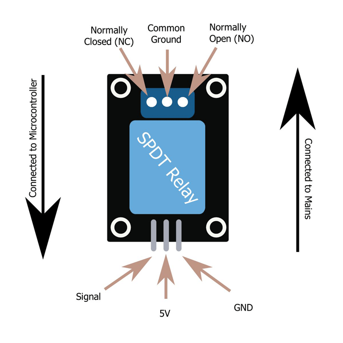
Relays have two kinds of terminals: one that’s high-voltage tolerant (think 220V) and another that only accepts low-voltage output.
When you pass an electric current through the low-voltage pins, you’re powering an electromagnet that pulls a “switch,” turning it either on or off, depending on the configuration you’re using.
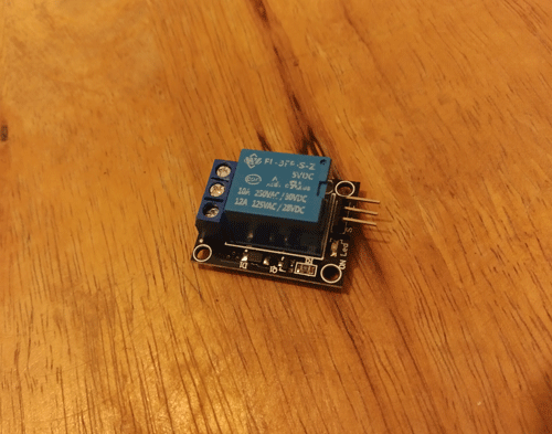
An SPDT relay always has six pins: typically with three male headers for connection to the Arduino and three screw terminal pins to connect to mains electricity.
Connecting the Relay Module to Arduino
The relay module should have header pins on it with three signs: Signal, 5V, and GND. These are the pins that you’re supposed to connect to the Arduino with jumper wires.
The pins work as follows:
- Signal: turns the relay on or off.
- 5V: accepts 5V to power the relay.
- GND: connects to Arduino’s GND pin.
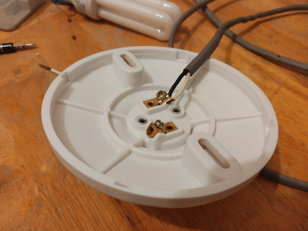
Connecting the Relay Module to a Light Bulb
On the other side of the relay module, there’s a screw terminal with three holes. It should have three signs: NC, NO, and Common Ground. Each hole connects to a copper wire that carries high-voltage electricity to and from the light bulb.
These holes do the following:
- NC (normally closed): connects to light bulb; closed while relay is off.
- NO (normally open): connects to light bulb; open while relay is off.
- Common Ground: connects to mains source.
You can only have either NC or NO connected to the light bulb – never both at the same time. If you do that, it’ll never turn off, as electricity will just pass through the other wire.
Warning: If you’re using relays, you’re messing with high-voltage electricity. This can be dangerous, as you risk shocking yourself. Please be careful and take safety precautions at all times. If you are not 100% sure what you are doing, it’s best to abandon the project until you learn more about working on it safely. Alternatively, consider enlisting the help of someone who knows their way around relays.
Choosing a Relay Module
Your local electronics dealer might have many different kinds of relay modules on the shelves. Unfortunately, most of these that are commonly available don’t work with an Arduino.
If you are shopping online, you should pick one that has “5VDC” in its model name. An example would be SRD-05VDC-SL-C, which is an SRD type 5V relay module.
Another thing to check is whether it’s an SRD or SSR relay. SRD relays are significantly cheaper than SSR relays at roughly half the price, but the benefit of them is that they’re silent when they turn on and off. SRD relays make a loud, clicky sound when their electromagnets shift between these positions.
Lastly, you should get one in module form. Normal SPDT relays don’t have pins that connect to microcontrollers. You’ll need these to connect it to your Arduino.
What You’ll Need
Here is the full list of items you’ll need before getting started with a relay module with your Arduino:
- SPDT 5VDC relay
- Arduino (any model)
- Copper cable (12 AWG should do, length depends on how long you’d like it)
- A light bulb
- Light bulb socket
- AC power plug
On top of that, you’ll need to have a few extra tools at hand:
- Wire cutter, to cut wires to your preferred length.
- Screwdriver, to loosen and tighten screw terminals.
- Wire stripper, to strip plastic housings off wires.
Using a Relay Module With an Arduino
Once you have all of the needed equipment, create your setup.
1. Prepare the Load
The “load” is the part of a circuit that consumes electrical energy in the form of the current and transforms it into other forms, like light and heat. For the purposes of this tutorial, we are using a light bulb as a load.
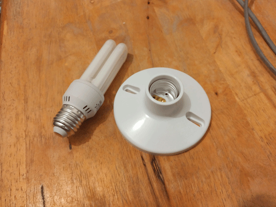
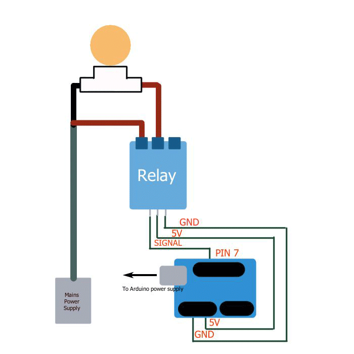
- Between the electrical plug and the light bulb, you should have a pair of cables. One cable goes straight from the electrical socket to the light bulb. The other gets cut up somewhere midway and connected to the relay module. Measure the lengths that you’d like to use.
- With a wire stripper, expose about an inch of wire on both sides. The light bulb socket and relay should have screw terminals for you to fit these on.
- Cut up the cables according to your measurements. The distance of the relay module from the load doesn’t matter here – what does matter is that you have enough cable length to reach the nearest AC outlet.
- Screw one of the plug’s cables into one of the socket’s screw terminals. Leave the other cable free for now.
- Screw the other cable to the relay: you can opt for either NC or NO.
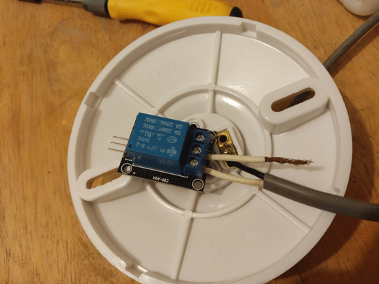
- Screw another wire to the terminal between NC and NO.
- Connect the other piece of cable to the light bulb socket’s screw terminal to complete the circuit.
2. Prepare Your Arduino
- Open the Arduino IDE and paste the following code. Don’t worry, as we’ll go through what each line does later.
const int relayPin = 7;

void setup() {
	pinMode(relayPin, OUTPUT);
}

void loop() {
	digitalWrite(relayPin, HIGH);
	delay(1500);
	digialWrite(relayPin, LOW);
	delay(1500);
}
Note: this code should work on ALL Arduino and 5V-tolerant Arduino-based boards.
- Save it to something like “arduino-relay.ino,” but anything will work as long as it ends with the “.ino” filetype.
- Upload the code to the Arduino. Use the USB cable that came with your Arduino board to connect it to your PC.
- Go to “Sketch -> Upload” or press CTRL + U on the keyboard to begin uploading.
- If you are a PlatformIO user, the “Build and Upload” button is in the blue tray at the bottom between the check and trash can buttons. It’s the arrow that points right.
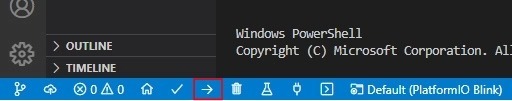
- If everything goes according to plan, you should get a “Done Uploading” notification on the Arduino.
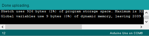
- Disconnect your Arduino from the PC.
Understanding the Code
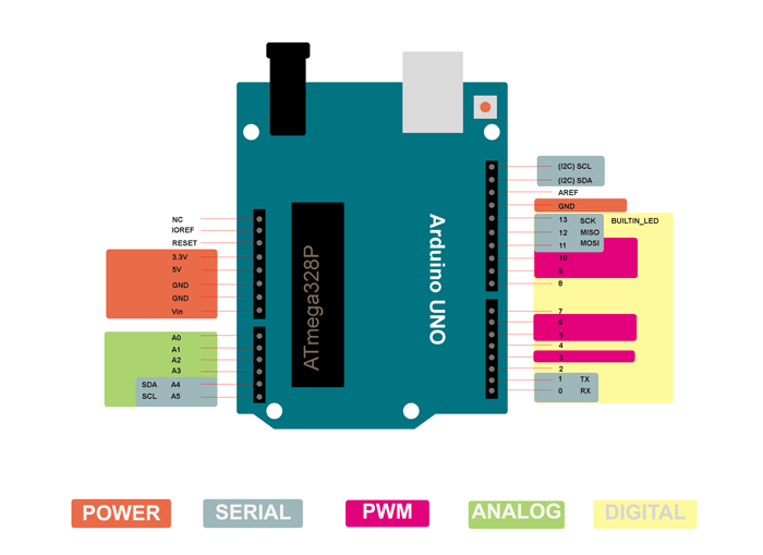
The first line in the code is used to define the pin used in this setup. Pin 7 is easy to find on the Arduino, so we are using that.
const int relayPin = 7;
const: defines something that will not change throughout the code.intindicates it’s going to be an integer.relayPin: is the name of an unchangeable number we are defining. We will use this later to call this unchangeable number.-
7: is the value of relayPin and the unchangeable integer.
void setup() {
	pinMode(relayPin, OUTPUT);
}
void setup() {...}: this function lets you run code once. Here, we defined what therelayPinaka pin 7 does.
pinMode(): a function that takes in two parameters: the pin number and whether it is an input or output. By default, all Arduino pins default as inputs except for the power pins. Here, we are instructing Arduino to allowrelayPinto become an output pin.
void loop() {
	digitalWrite(relayPin, HIGH);
	delay(1500);
	digialWrite(relayPin, LOW);
	delay(1500);
}
void loop() {...}: lets you run your code indefinitely.digitalWrite(): takes in a pin number and turns it to eitherHIGHorLOW. A pin onHIGHemits 5V while a pin onLOWsits at 0V. By sending 5V from the Arduino to the relay’s magnetic coils, we are effectively powering a tiny electromagnet with 5 volts.delay(): pauses the whole code. It takes a number as a parameter, which is how long you want to pause the code in milliseconds. In this case, we’re pausing the code for 1500 milliseconds each or 1.5 seconds.
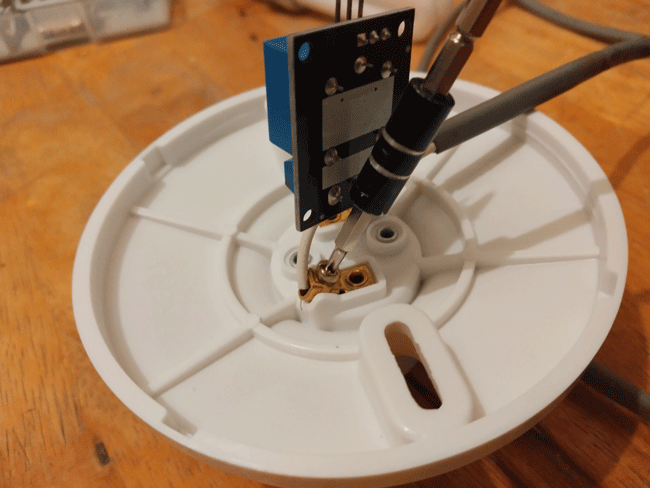
3. Connect to Your Arduino
In the final step, you’ll be connecting the load to the Arduino.
- Using jumper pins, connect each terminal from the relay to each Arduino pin as follows: IN to Pin 7, VCC to 5V and GND to GND.
- To make this all work, connect the electrical plug to the AC socket and connect the Arduino to a 5V power supply. This can be a power bank, DC battery, or a power adapter used for phones.
Note: when messing with things that could potentially break your computer (your Arduino included), it’s always a good idea to connect the board to a power supply that’s NOT your computer’s USB port.
- The light bulb should light up and die down every 1.5 seconds. You can tweak the code to make it do other things or connect it to sensors.
Frequently Asked Questions
What does SPDT stand for in relays?
SPDT stands for single pole, double throw. On a circuit, poles are paths for things you are connecting to and consist of a route from the power source to the load. Meanwhile, throws are the number of ways to connect poles. An SPDT relay has a single pole but two ways (throws) to connect them (one ending in NC and another ending in NO).
What is the pickup voltage of a relay?
Pickup voltage refers to how many volts you need to make the relay’s electromagnet pull the switch over to its side. If the voltage is too low, the electromagnet won’t have enough strength to pull.
What pickup voltage do I need for a relay using Arduino?
The Arduino can release 5V through its output pins. Any relay with a pickup voltage lower than 5V should work.
All screenshots by Terenz Jomar Dela Cruz.
Get the best of IoT Tech Trends delivered right to your inbox!


