
Arduino hardware is great for IoT projects, but if you’re just getting your feet wet, it can be a little confusing. Much of the code you’ll need to write is straightforward, but once you have to interact with different hardware, the code can start getting more complex.
PWM pins are a great example of this. They enable you to work with a variety of different hardware and control it in many ways, but if you don’t come from an electrical background, they can seem tough to deal with.
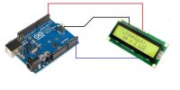
Also read:How to Interface an LCD Screen in Arduino
What Does PWM Do on Arduino?
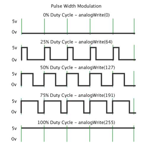
PWM stands for Pulse Width Modulation. This is a digital square wave where the frequency stays the same, but how often that signal is being sent is adjustable. Without context, that doesn’t mean much.
Pulse Width Modulation lets you do many useful things. This includes sending audio signals, controlling variable speed motors, or providing variable current to dim LEDs and similar functions.
Can’t You Just Use the analogWrite() Command?
For most users, the analogWrite() command will do all you need, but as mentioned above, the frequency is fixed. This is fine for many use cases, but not all of them.
Each pin has a default frequency. This differs per pin, but they are still within a fairly close range of one another. The highest default frequency is still under 1,000 Hz, which isn’t enough for all use cases.
Manipulating PWM Timers Directly
You can manually set PWM frequencies by manipulating the time registers. There are a total of three of these, each controlling two PWM outputs each, Timer 0, Timer 1, and Timer 2. There are two ways to control the frequencies: Fast PWM, and Phase Correct PWM.
Below is an example of Fast PWM from the Arduino website:
pinMode(3, OUTPUT);
  pinMode(11, OUTPUT);
  TCCR2A = _BV(COM2A1) | _BV(COM2B1) | _BV(WGM21) | _BV(WGM20);
  TCCR2B = _BV(CS22);
  OCR2A = 180;
  OCR2B = 50;
This would yield a frequency of 976.5625Hz, using the following math:
Output A frequency: 16 MHz / 64 / 256 = 976.5625Hz
Output A duty cycle: (180+1) / 256 = 70.7%
Output B frequency: 16 MHz / 64 / 256 = 976.5625Hz
Output B duty cycle: (50+1) / 256 = 19.9%
Below is an example of Phase Correct PWM from the same website:
pinMode(3, OUTPUT);
  pinMode(11, OUTPUT);
  TCCR2A = _BV(COM2A1) | _BV(COM2B1) | _BV(WGM20);
  TCCR2B = _BV(CS22);
  OCR2A = 180;
  OCR2B = 50;
This provides an output frequency of 490.196Hz, using the following math:
Output A frequency: 16 MHz / 64 / 255 / 2 = 490.196Hz
Output A duty cycle: 180 / 255 = 70.6%
Output B frequency: 16 MHz / 64 / 255 / 2 = 490.196Hz
Output B duty cycle: 50 / 255 = 19.6%
Manually Controlling PWM Pin Frequencies
Another option is to manually switch a pin on and off at the desired rate. The bonus here is that it lets you use any pin, not just the dedicated PWM pins.
Here is another example from the Arduino website:
void setup()
{
  pinMode(13, OUTPUT);
}

void loop()
{
  digitalWrite(13, HIGH);
  delayMicroseconds(100); // Approximately 10% duty cycle @ 1KHz
  digitalWrite(13, LOW);
  delayMicroseconds(1000 - 100);
}
There are a few issues with this method. One is that interrupts will affect the timing, which could cause problems. You’re also effectively limiting the Arduino to just doing this while it is running.
Conclusion
Now that you understand how to change the frequency of PWM pins on an Arduino board, you’ve opened up a lot of options. To see just how much you can do, why not get started building something?
If you’re new to Arduino in general, you’ll probably still run into the occasional stumbling block along the way. If that’s the case, be sure to keep our Arduino cheat sheet within reach.


