
The project includes the use of an Ultrasonic Sensor to control LED glow patterns using Arduino UNO R3. This is a single sensor-based application to demonstrate the processing and control power of Arduino. It also highlights the input-output (I/O) mechanism and its communication with the ATmega328P microcontroller.
Understanding the Input/Output (I/O) of Arduino Uno
Let’s understand the (I/O) pins of the Arduino Uno board before starting with anything else. In computing, input/output is the communication between an information processing system, such as a computer, and the outside world, possibly a human or another information processing system. Hence, inputs are the signals or receiving data and outputs are the signals or sending data.
The Arduino UNO R3 board comes with a set of digital and analog input/output (I/O) pins. These allow PWM, RXT, TXD, GPIO, and I2C pin activities. Also, there are in total 14 Digital pins and 6 Analogue pins on the Arduino UNO R3 board. The use of analog pins is alternatively for digital pin configuration.
Project Description
This project helps you to get a clear understanding of the Arduino board and its I/O pins, configuring a sensor to communicate with the board, writing a proper code to produce the desired output based on the input from the sensor.
The following are the components required to perform the application:
- Arduino Uno R3 board
- BreadBoard
- Ultrasonic Sensor
- LEDs – 6 units
- 220Ω resistors – 2 units
- Connecting Wires
Let’s understand more about the major components for this project, before beginning the implementation
Arduino Uno R3 Board
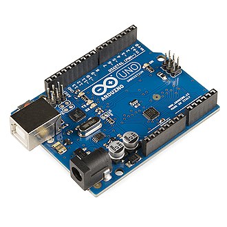
The Arduino Uno board features a series of microcontroller boards for various applications. Due to its simple design, universal compatibility, and lower cost, has attracted people from various walks of life. The Arduino integrated development environment (IDE), is straightforward to understand and use. Thus, Arduino UNO proves to be a good tool to get your hands dirty and gain valuable experience in building small projects for beginner-level IoT enthusiasts. Also, it finds its place in the basic inventory of some highly sophisticated IoT projects.
Ultrasonic Sensor
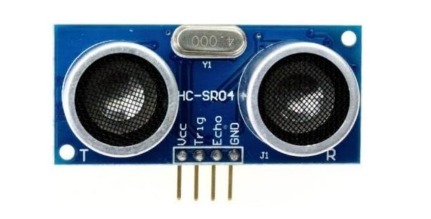
An Ultrasonic sensor is a device that can measure distance by using sound waves. It measures distance by sending out an ultrasonic sound wave which then reflects back from an object placed in front of it. The sensor then calculates the time difference between the sending and receiving of waves and converts it to distance.
Algorithm for the Use Case
After gathering the required components, it’s time to implement a circuit doing the following:
- When the distance of an object from the US Sensor is greater than 15cms, the LEDs glow in a clockwise pattern.
- Whereas, when the distance of an object from the US Sensor is less than 15cms the LEDs glow in an anticlockwise pattern.
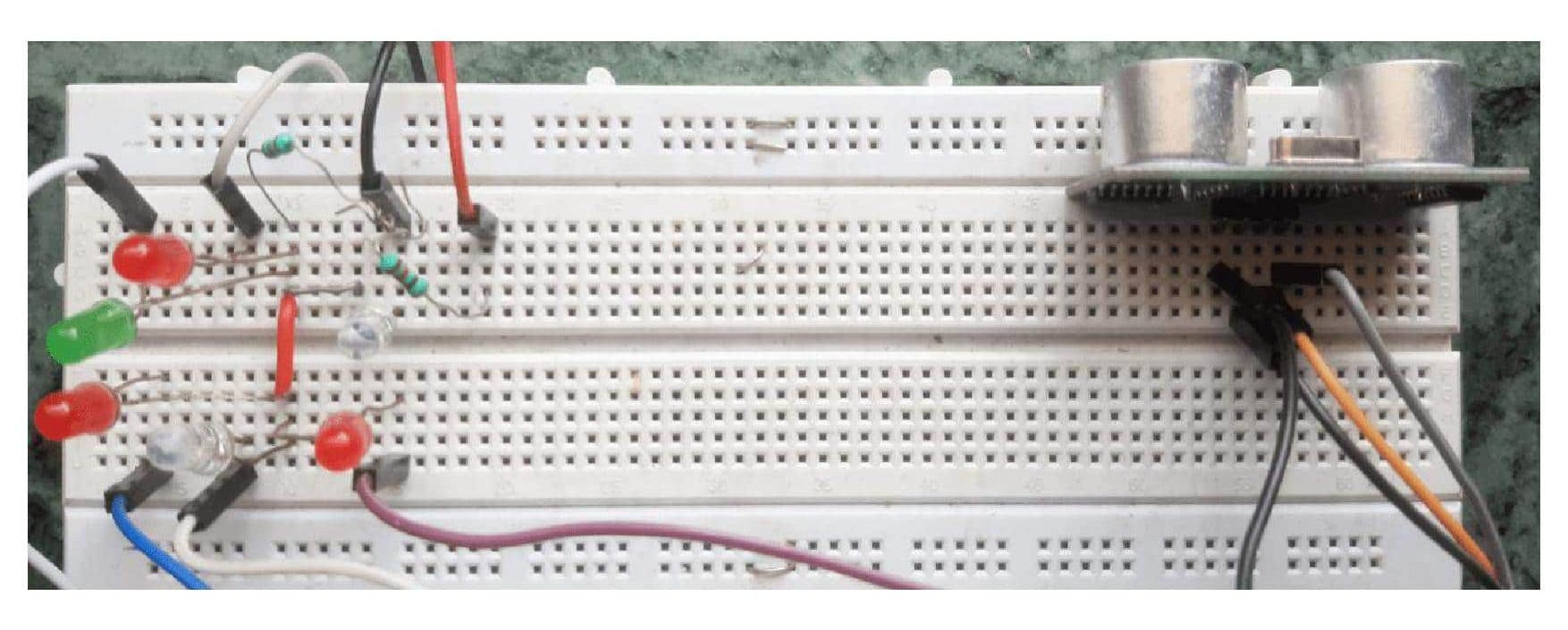
Connecting the Components with Arduino Uno
Place the LEDs on the breadboard in a circular pattern connected through two 220Ω pull-up resistors in common. Connect the common terminal to the +Vcc of the Arduino board. Then connect the other terminals of LEDs to digital pins 5,6,7,9,10,11 of the Arduino board following the circular pattern.
Now, place the Ultrasonic Sensor on the breadboard and provide the +Vcc and GND connections to it. Then connect the sensor’s Echo and Trigger pins to pins 12 and 13 of Arduino.
Arduino IDE Setup
Install the Arduino integrated development environment (IDE) software on your PC.
Then connect the Arduino board to the PC using the USB cable. Set the board as “Arduino UNO” and port to which your board is connected in the “Tools” menu of the IDE. You can find the port number by going to the “Device Manager” window on your Windows PC.
Programming on Arduino Uno
Now, create a new sketch on Arduino IDE and write the code accordingly. You can also customize the code according to your requirements with respect to the I/O pins of the Arduino UNO R3 board.
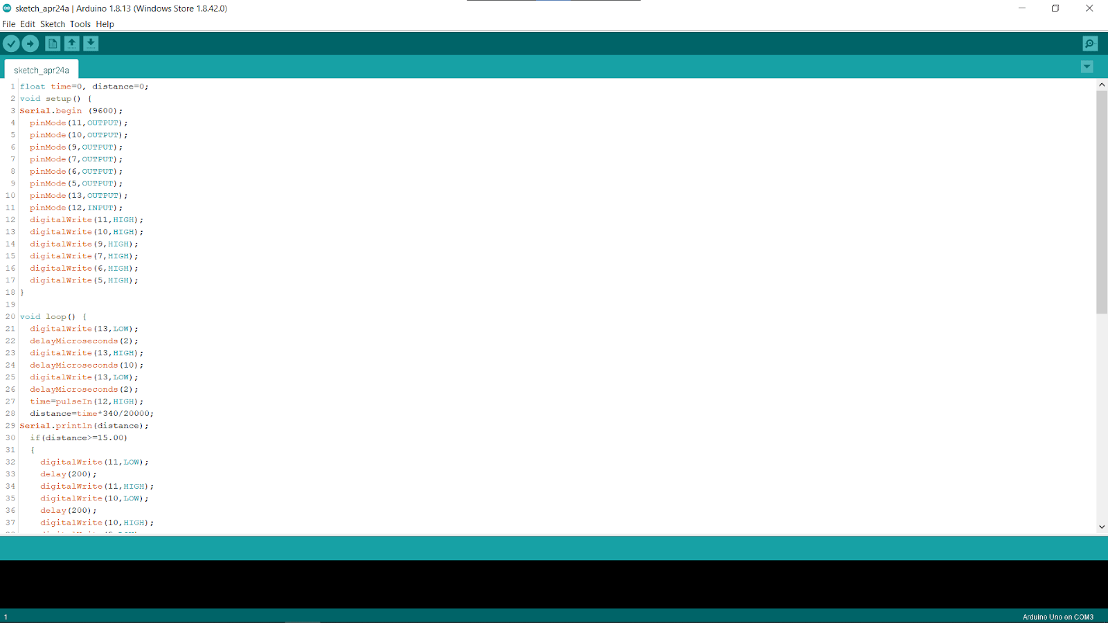
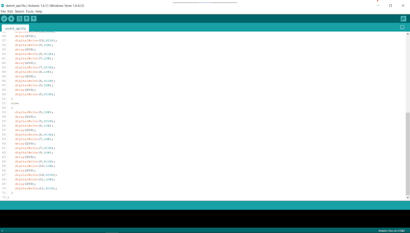
Complete Code for Implementation
You need to copy the below code and paste on your Arduino IDE editor.
float time=0, distance=0;
void setup() {
    Serial.begin (9600);
    pinMode(11,OUTPUT);
    pinMode(10,OUTPUT);
    pinMode(9,OUTPUT);
    pinMode(7,OUTPUT);
    pinMode(6,OUTPUT);
    pinMode(5,OUTPUT);
    pinMode(13,OUTPUT);
    pinMode(12,INPUT);
    digitalWrite(11,HIGH);
    digitalWrite(10,HIGH);
    digitalWrite(9,HIGH);
    digitalWrite(7,HIGH);
    digitalWrite(6,HIGH);
    digitalWrite(5,HIGH);
}

void loop() {
    digitalWrite(13,LOW);
    delayMicroseconds(2);
    digitalWrite(13,HIGH);
    delayMicroseconds(10);
    digitalWrite(13,LOW);
    delayMicroseconds(2);
    time=pulseIn(12,HIGH);
    distance=time*340/20000;
    Serial.println(distance);
    if(distance>=15.00)
    {
        digitalWrite(11,LOW);
        delay(200);
        digitalWrite(11,HIGH);
        digitalWrite(10,LOW);
        delay(200);
        digitalWrite(10,HIGH);
        digitalWrite(9,LOW);
        delay(200);
        digitalWrite(9,HIGH);
        digitalWrite(7,LOW);
        delay(200);
        digitalWrite(7,HIGH);
        digitalWrite(6,LOW);
        delay(200);
        digitalWrite(6,HIGH);
        digitalWrite(5,LOW);
        delay(200);
        digitalWrite(5,HIGH);
    }
    else
    {
        digitalWrite(5,LOW);
        delay(200);
        digitalWrite(5,HIGH);
        digitalWrite(6,LOW);
        delay(200);
        digitalWrite(6,HIGH);
        digitalWrite(7,LOW);
        delay(200);
        digitalWrite(7,HIGH);
        digitalWrite(9,LOW);
        delay(200);
        digitalWrite(9,HIGH);
        digitalWrite(10,LOW);
        delay(200);
        digitalWrite(10,HIGH);
        digitalWrite(11,LOW);
        delay(200);
        digitalWrite(11,HIGH);
    }
}
Verify and Upload the Code
Now you need to verify the code by pressing the verify button on the Arduino IDE toolbar. Wait for the code to verify. Once verified, you can see a “Done compiling” message on the screen.
If there are no errors found, then upload the code using the upload button beside the verify button. Wait for the code to get uploaded and then the circuit will start working. You will also see a “Done uploading” message on the screen. Refer to the following section which explains the code.
Code Explanation for Interfacing Ultrasonic Sensor with Arduino Uno
The logic of the code is built in such a way that its implementation will give in depth knowledge on the customization of the I/O pins depending on your case. Below are the detailed explanation of both the functions used in the code for a better understanding of the logic and the flow of the project.
Void Setup
The void setup function runs once initializing all the required pins on the Arduino board.
LEDs are connected to digital pins 5,6,7,9,10,11 of the Arduino board. These LEDs are in an active low configuration i.e. when the input signal is low, LED is turned ON.
Ultrasonic sensor’s Echo and Trigger pins are connected to pins 12 and 13 of the Arduino respectively.
Void Loop
The void loop function runs the code repeatedly. First, the Ultrasonic Sensor sends an Ultrasonic Wave which reflects back from the object in front. Then the Arduino board calculates the time interval between sending and receiving of the wave and converts it into the distance which is then stored in the distance variable.
Now, depending on the distance value, execution of the if and else condition statement takes place. So, if the “distance>=15.00” condition is true, the if block statements for glowing of LEDs in a clockwise pattern are executed. And if the condition is false, the else block statements for glowing of LEDs in an anticlockwise pattern are executed. Hence, the delay lines in the program help in the rhythmic control of glowing LEDs.
Conclusion
Now that you understood the complete logic and flow of this project. You can build your own project application by interfacing the ultrasonic sensor to the Arduino Uno R3 board and play around with the I/O ports.
If you haven’t set up Arduino IDE on your local machine. check out the article on how to configure Arduino IDE on Windows.


